justinalanbuckley
New Member
- First Name
- Justin
- Joined
- Sep 16, 2024
- Threads
- 2
- Messages
- 4
- Reaction score
- 0
- Location
- Asheville, NC
- Vehicles
- R1T
- Occupation
- IT
- Thread starter
- #1
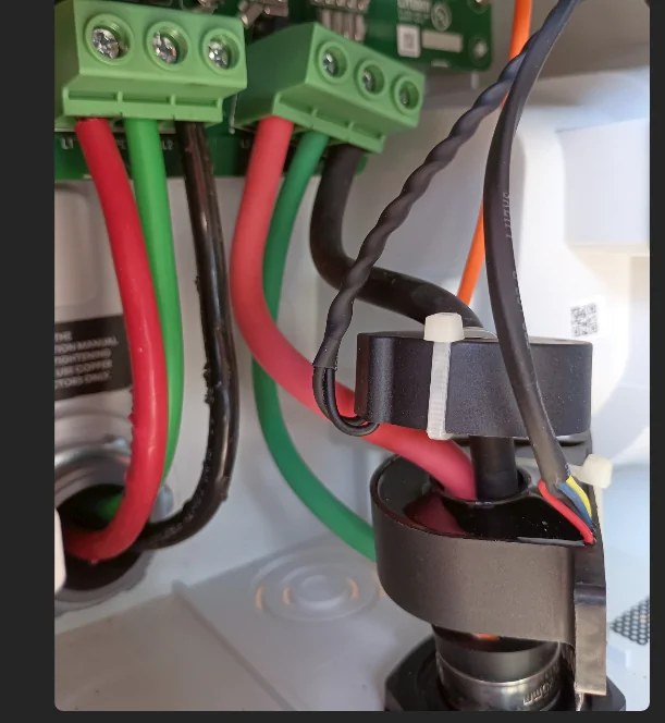
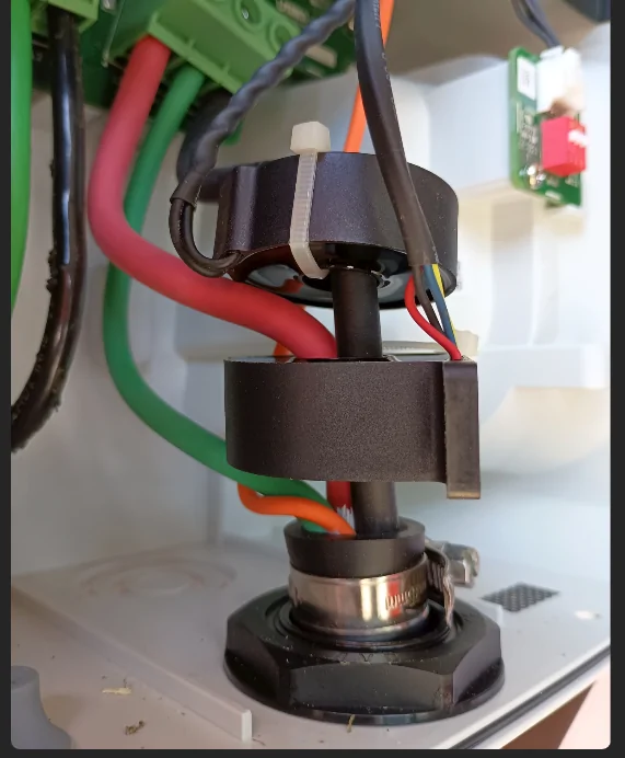
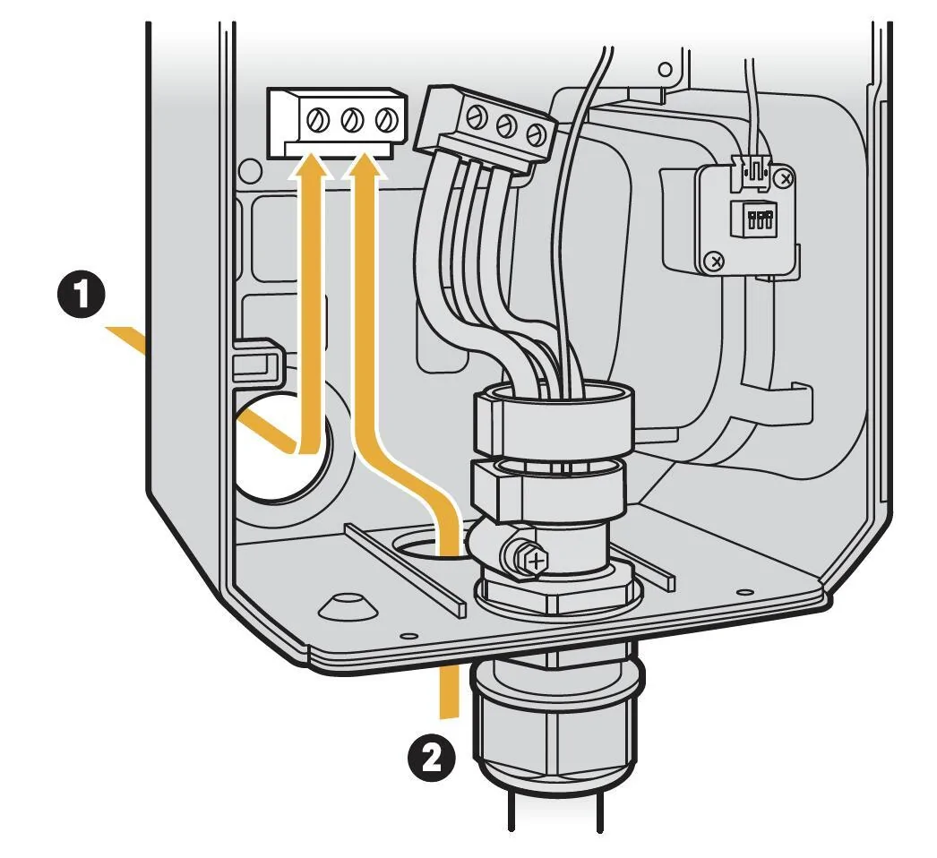
Hello all. First post here - recently picked up a 2022 R1T Launch Edition that came with the Rivian Wall Charger. However, the charging cable was disconnected from the box and I'm trying to verify how it would have been originally wired. The instructions show all the conductors from the charging cable passing through the 2 black circular devices that I assume measure the current being drawn when charging (see image below). However they are far too small for that. Also when looking around online at other tutorials, it appears that maybe only the red and black pass through these?
Can anyone confirm for me exactly which conductors are suppose to be fed through these loops? Note that one of them has mounting tabs and the other does not (however I don't any place to mount the one with tabs).
Thanks in advance!

Can anyone confirm for me exactly which conductors are suppose to be fed through these loops? Note that one of them has mounting tabs and the other does not (however I don't any place to mount the one with tabs).
Thanks in advance!
Sponsored